RPS-SP4L – Remote Power Control Instructions

Screen Shots and RPS-SP4L Configuration.

Status – Main Screen

Click to Enlarge
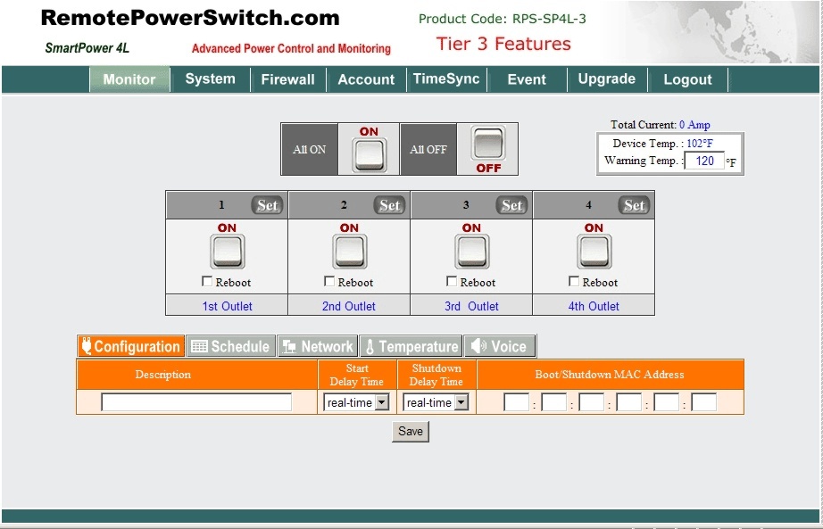
The main screen allows direct control of the individual electrical ports on the back of the unit. Prompts are available that will help you through each step by hovering your mouse over the appropriate button.

Double clicking on the control button will activate the power on / off functions. As you can see there are options for ALL ON, ALL OFF and also to control the individual ports. Up to 4 user accounts ( Tier 3 Software) are available with access only to the designated ports. This is configured in the ACCOUNT menu.

If the Reboot option is selected on the individual ports, clicking on the button will initiate a reboot instead of a power on or power off control. You can also go into the SYSTEM > OTHER and select the reboot option to enable this option by default.

NOTE for individual ports, you have to select the SET button for the port you want to control before proceeding. This activates the available options for the port. Some options will not be available depending on the version of the RPS-SP4L unit you have purchased.

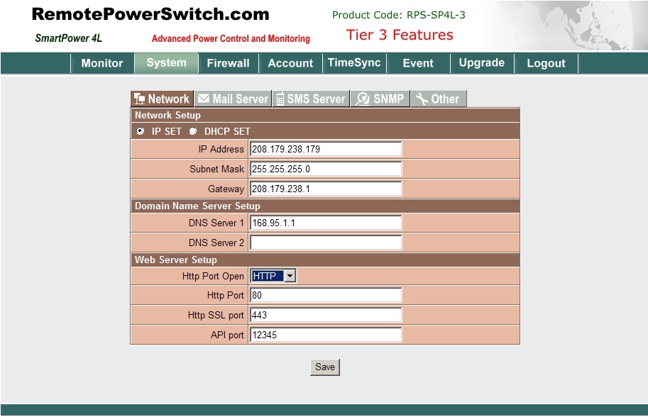
To begin configuration of the unit after inital login it is best to go to SYSTEM > NETWORK Screen to check the configuration of the IP Address for the unit. ( For further information on this home page menu, click here.)

SYSTEM > NETWORK

Click to Enlarge

On this screen a STATIC IP Configuration can be enabled by selecting the IP SET radio button. DHCP can also be enabled. The RPS-SP4L ships from the factory with a static IP of 192.168.1.10 and DHCP disabled.

Enter your network configuration, DNS Server(s) and configure your active HTTP port. You may chose an alternative port instead of standard port 80 by entering the port number into the box. Note that you will have to append the port number to your https:// command line in your browser to be able to reach the login screen of the RPS-SP4L. An example would be https://192.168.1.10:8181 if port number 8181 was placed into the above HTTP Port entry. Note the colon followed by the port number in the command line.

The API Port is presently disabled. Contact our sales department for further information.

Please make sure you click the SAVE button to save your configuration.


SYSTEM > MAIL SERVER
Configuration of Outgoing Email Notifications
(Tier 2 and Tier 3 Versions of RPS-SP4L Only)

Click to Enlarge

The above screen allows you to configure the outgoing mail server

SMTP Server Address: Enter in your mail server address. Example: mail.YourDomain.com
SMTP Port: The connect port for your email server typically port 25.
Sender Mail Address: This is the email address you wish to use for the RPS-SP4L unit. It will appear
as the FROM address in the outgoing email.
Subject
: The subject line of the outgoing email notification.
SMTP Auth: If your outgoing email server requires authentication, check off this box.
SMTP Account: The Email Account authorized to send email to the mail server.
SMTP Password: The password for the authorized account.

Remember to click the Save Button.

Configuration of Outgoing SMS
(Tier 3 Version of RPS-SP4L Only)

Click to Enlarge

Server Address: The SMS Server that will be receiving the outgoing message.
Port: The SMS server connect port typically 2500.
Equipment Name: This name will be included in the SMS message and identifies this device.
Account: SMS Account Name for sending messages.
Password: Password for the SMS account
Send SMS: Check off this box to enable SMS messages. Please remember to click the save button to save
your configuration to the RPS-SP4L unit.